Alt-F4 #24 - Creating Memories 2021-02-19

This week, we’re following up on pocarski’s piece from last week that was all about how to build a computer inside Factorio using only belts. This time, we’re trying to teach it how to remember things. Let’s see how that goes.
Belt-only Computing, Part 2: Never Forget pocarski
This week, I’ll continue with the continuation of my article about belt-only computing. I highly advise going back to the previous issue for a refresher.
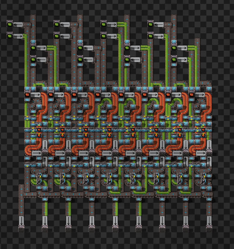
A short note before we begin: during the week Discord user BlueCheetah#7844 made significant layout improvements to my adder circuit, it is now slightly longer, but four tiles wide. Here’s an image of it doing the same math as last week:
With that out of the way, let’s get down to business. Last time, we explored adding numbers using only belts and splitters, and this week we will look at something just as important when it comes to computing: memory. The ability to add numbers is neat, but ultimately useless if there is no way to store the instructions or the result. Inside a CPU, the results of addition are remembered and then, after some manipulation, fed back to the same adders that just calculated them. This allows for pretty much every imaginable mathematical operation.
Just like last week, everyone is welcome to have a hands-on experience with a blueprint book with all the circuits from this article.
The multiplexer
To start off, we will introduce a new circuit: the multiplexer. A multiplexer has two data inputs A and B, one pointer input P and one output O. Here is the truth table for this multiplexer (“-“ means input doesn’t affect output):
| A | B | P | O |
|---|---|---|---|
| 0 | - | 0 | 0 |
| 1 | - | 0 | 1 |
| - | 0 | 1 | 0 |
| - | 1 | 1 | 1 |
Input P effectively chooses which of the data inputs should be passed to the output. If P is 0, our output will equal the value of A, and if it is 1, our output will be the value of B. Now, to actually build this, we can make use of AND gates. They allow us to selectively ignore an input. We can choose whether we want to pass through an input or not by simply enabling or disabling the gate’s other input. With this in mind, we can reimagine the multiplexer as (A AND NOT P) OR (B AND P). All of those are elements that we’re already familiar with, which means a multiplexer can be built like this:
This is simply a duplicator-NOT circuit and two AND gates. We also need some item swappers, to match all input and output item types.
Basic memory cell
Memory cells sound very complicated at first. A circuit that remembers an input? Surely that would need some kind of storage, and how do you make it output without the storage running out? This is where our new friend the multiplexer comes in. What happens if we loop the output all the way around and feed it into its own input A? The answer is: magic happens!
As you can see, with this single change we transformed the multiplexer into a very basic memory cell. What used to be input B is now the sole data input into the memory cell, and what used to be input P is now the “write” input. This circuit doesn’t have an output since we looped it, so we fix that by adding a duplicator (and also combining a swapper with an AND, just like last time):
This circuit we just made is called a D latch. It has two inputs: D for “Data”, and E for “Enable”. Unlike in electronic computers, we have to keep E turned on for quite some time, since the items need to make their way back to the beginning for the output to become stable. However, a D latch has a pretty significant issue, that being, while input E is on, the output completely copies input D, effectively turning the entire thing into a fancy wire. We need to guarantee output stability, and for that, we need something more than a simple D latch.
Master-slave memory cell
Many problems can be solved by just building another copy, and the D latch’s issue is no exception. We duplicate and invert input E, and feed its inversion into another D latch’s enable input. Then, we make the first latch’s output go into the second one’s data input. The inversion here is done by introducing a third item type, which gets overridden by the enable input. Just like last week, the two sides of belts come to the rescue, and we don’t actually need to build a whole other copy, we can just do some clever looping:
This double latch system creates a sort of staircase for our data value, where it’s allowed on the first step when input E turns on, and allowed to keep going only after it turns back off. This protects the output from changing until we have completed a cycle. Now we can rearrange everything to make a compact module:
Interestingly, it has the exact same dimensions as last week’s adder module (or it used to until BlueCheetah came along). Talk about a satisfying coincidence!
Final note
Now that we have an adder and memory, we’re all set to build a CPU. Of course, we need a clock to run everything, but that is as simple as a half-full belt loop with a duplicator. The arithmetic logic unit (ALU) is just a bunch of adders looping back into themselves through a register, which in itself is just a bunch of memory cells. My knowledge of computer science is not extensive enough to explain everything fully, so please consider checking out letao12 on YouTube, as it was his series that inspired me to give this belt-based logic a try.
Contributing
As always, we’re looking for people that want to contribute to Alt-F4, be it by submitting an article or by helping with translation. If you have something interesting in mind that you want to share with the community in a polished way, this is the place to do it. If you’re not too sure about it we’ll gladly help by discussing content ideas and structure questions. If that sounds like something that’s up your alley, join the Discord to get started!