Alt-F4 #31 - Combinator Crash Course 16-04-2021
After a quick one-week break, Alt-F4 is back with issue #31. In it, pocarski returns to talk about yet more ways to build computer logic in Factorio, featuring combinators this time, which turn out to be simpler to use than you’d think! Afterwards, Big Community Games announce another exciting event of theirs, this time with Industrial Revolution as the central focus.
Combinators and why you shouldn’t fear them pocarski
There are many technologies in the research tree that aren’t necessary to finish the game, and are therefore often sidelined. Some of those are perfectly understandable, for example military tech on peaceful mode. Others are sometimes not even considered, even though they can provide exceptional improvement. One such technology is the circuit network, which I will explore in this article.
There are four main components of the circuit network: wires, constant combinators, decider combinators and arithmetic combinators.
Constant combinators continuously output whatever you set them to (and also don’t need power); decider combinators output some signal when a certain logical condition is met; arithmetic combinators perform mathematical operations. Wires act like a sort of “signal cloud”, where all signals being output into a wire can be read by everything connected to it. Red and green wires have identical functionality, but can both be connected to the same device without interfering with each other.
Basic elements
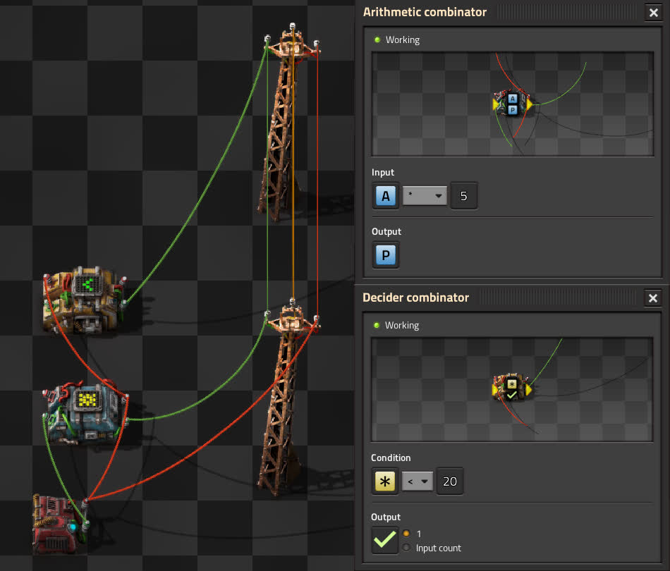
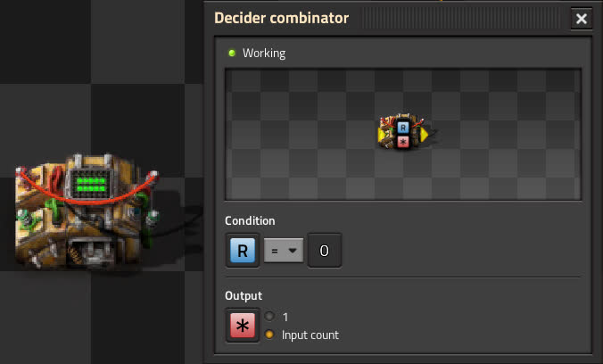
Let’s look at three very simple single-combinator modules which are widely used. These modules are: the pulser circuit, the RS latch and the counter. We’ll start with the pulser, which looks like this:
The pulser is the easiest to understand. The input is immediately passed to the output through the red wire, and the inverted input is added onto the same red wire after the standard one tick of combinator delay. Both values being on the same wire cancel each other out, meaning the output is exactly equal to the input, but only lasts for a single game tick. Here, use of the “each” signal makes sure that the circuit can take any signal as input. If you wish to make it signal-specific, you can replace the “each” in input and output with the desired signal. This circuit has a truly colossal amount of uses, especially if used in combination with a counter.
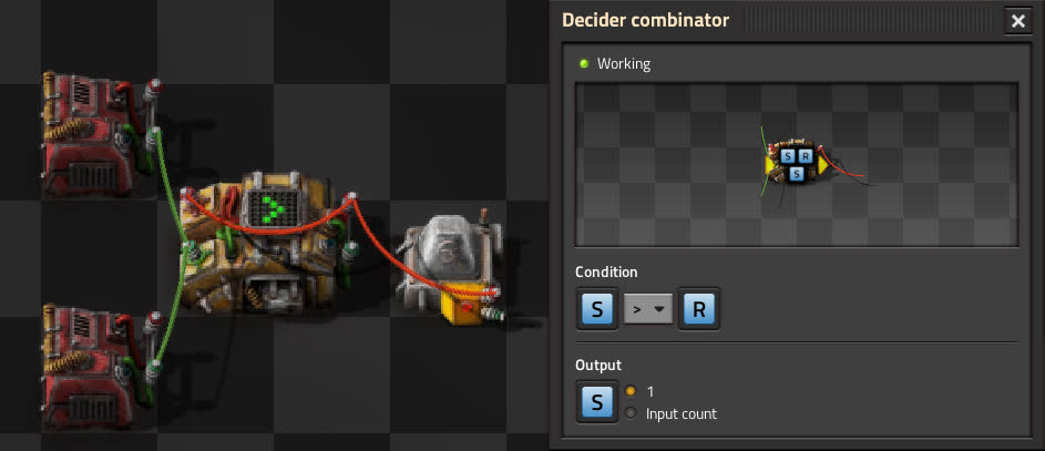
Next is the RS latch. Its inputs are either 1 “S” signal or 1 “R” signal, standing for Set and Reset. When it receives an “S” signal, the condition of the combinator becomes true. It is looped to itself, so the 1 “S” that it outputs will be added to the input, and keep the condition true even after the original “S” input turns off. Similarly, when it receives an “R” input, the condition becomes false, turning off the “S” output and breaking the cycle. This circuit is best used for systems where you want some kind of hysteresis, where one state triggers the “S” input, and another state triggers the “R” input.
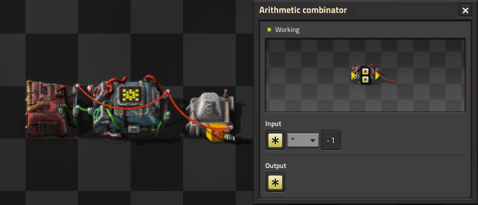
Finally, the counter. Structurally it is identical to the RS latch, but this time the output is set to “input count of everything”. This means that while the decider’s condition is followed, it will keep giving its own outputs to itself, thus remembering them. For every tick it receives a signal, it will increment the value of that signal in its memory by the amount received. As soon as the condition is broken, the memory is cleared, since the decider no longer allows signals to pass. Similarly to the pulser, if you wish to make it remember only one signal, replace the “everything” in the output with the desired signal. This circuit, just like the pulser, has an immense number of uses, but the most popular one is to keep track of item amounts.
Basic examples
Now, let’s explore some cases where each of these modules might come in handy.
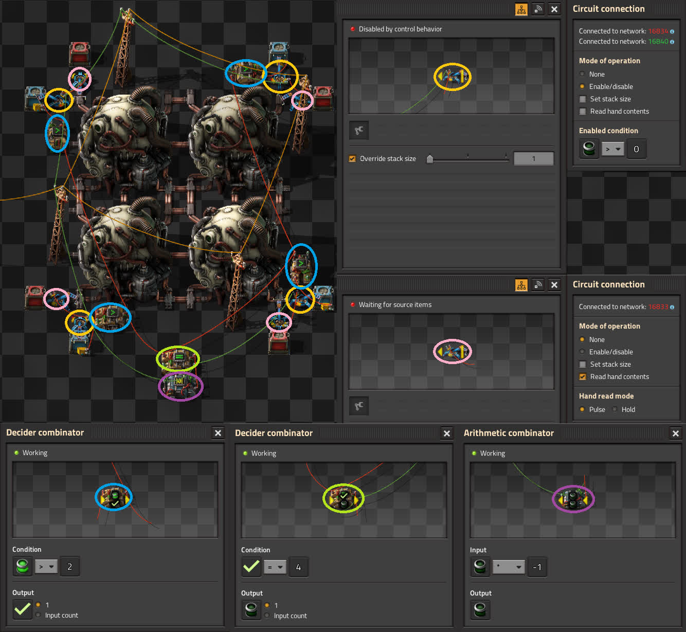
Say you have a nuclear reactor blueprint where the extraction of a used fuel cell triggers the insertion of a fresh one. Such a design would have to be manually started since reactors are built empty. What you ideally want to add is a circuit which, once all fuel cell chests have items in them, triggers the fueling inserters exactly once. This is where the pulser comes in. Have a combinator in each chest checking if there are enough items in it, and then wire all of those together into a single combinator that checks if all chests are ready. This decider then outputs a “used fuel cell” signal into a pulser, which is wired to every fueling inserter of the reactor. This causes all fueling inserters to trigger exactly once the moment there is fuel available to all of them, starting the reactor automatically. By extension, this also makes the reactor automatically restart if it ever runs out of fuel.
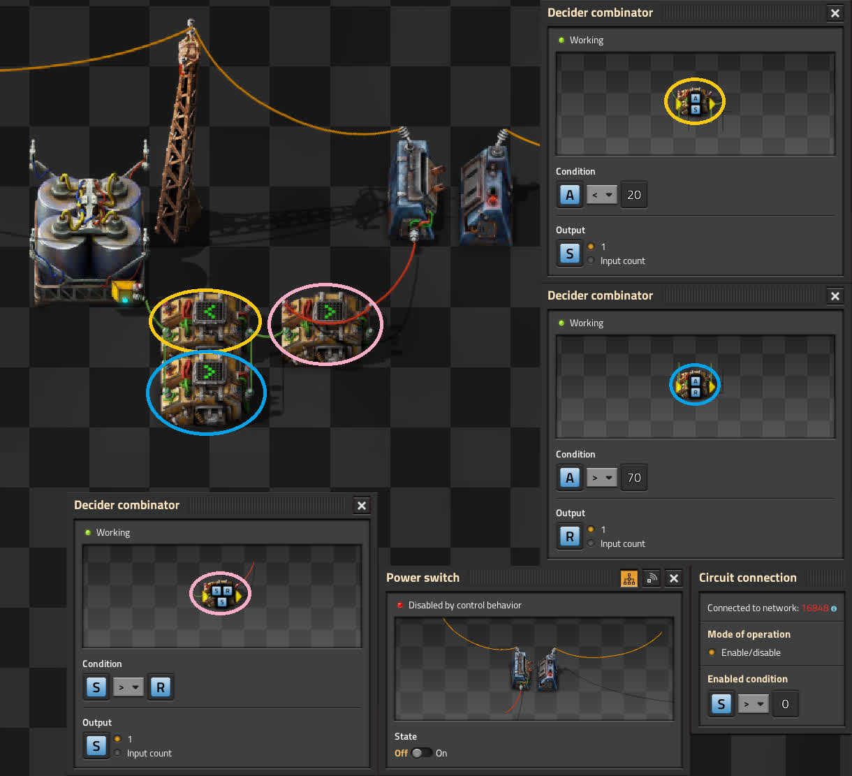
Next, a classic example: backup power. Imagine you have an array of accumulators and you want to activate your boilers if the stored energy gets too low. You could just wire a switch directly to an accumulator and tell it to activate if accumulators are below, say, 20% charge, but that would just cause it to rapidly switch on and off, keeping the accumulators at exactly 20% all the time. Instead, you should use an RS latch. Have a combinator output “S” when accumulator charge is below 20%, and another one output “R” when charge is above 70%. Hook them both to the latch, and wire the output of the latch to a switch set to activate if S > 0. The switch will activate as soon as charge drops below 20%, and keep the backup running until charge rises above 70%.
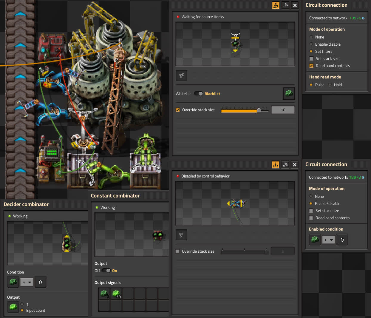
Finally, a process that many fear to set up: uranium enrichment. We need to look at 3 inserters: input, output, and recycling. That last one isn’t a single inserter, but we only care about the first link of the inserter chain. Input inserter doesn’t need any control logic, it simply grabs 3 items of U-238 and loads them whenever they’re needed. Output inserter must be disabled while recycling happens, to not take out any of the catalyst items. Recycling inserter must take out exactly 40 U-235, as well as 2 U-238. The recycling inserter is receiving a constant signal of U-238, which makes it blacklist it. It begins to take out U-235, and increments the counter by the grabbed amount every time it does. The inserter is also receiving a constant signal of -39 U-235, which doesn’t affect the filter. Eventually, the inserter will be reading 40 U-235 from the green wire, and -39 U-235 from the red wire. It now sees a positive total amount of U-235, and since U-235 is earlier in the signal list, it takes priority over the U-238 signal. The inserter now blacklists U-235, which means it switches to taking out the 2 items of U-238. This does two things: clears the counter and triggers the output inserter, which now has no choice but to take out the remaining U-235. The 2 recycled U-238 items will be inserted at the start of the next cycle. U-238 recycling doesn’t need any extra logic, because the input inserter is limited to a maximum of 3 items, leaving the other 2 spots for the recycled uranium.
Conclusion
Each of the given examples can be improved and made more specific to the user’s needs. Sometimes it can be done with basic math and logic, other times you’d need to add a couple more basic modules. For example, you could add a second counter to the enrichment circuit to prevent the centrifuge from overfilling and stalling if there’s some U-235 in the input stream.
Every single milestone in circuit networks was worked towards step by step, by splitting the whole into parts, and then splitting the parts even further. After all, that’s how modern computers were developed - make a logic gate out of transistors, then make a memory latch and an adder out of logic gates, then make a RAM and ALU out of memory latches and adders, then make a computer out of those. If you can manage to sometimes think “hey, I’ve solved this before”, then you can achieve anything with circuits.
Full steam ahead! T-A-R
Big Community Games is happy to announce another Factorio MMO event. A very ore-rich piece of Nauvis has been scouted, bringing us a great opportunity to launch a rocket together this very Saturday! The theme of this party will be Steampunk. Deadlock989’s Industrial Revolution 2 will bring all the steam and smouldering fuel we love, and possibly even a bit more.
Compared to vanilla, our toolbox gets expanded with all kinds of technologies. New materials and processes will make crafting the rocket a bit more complex in a very enjoyable way. The event page has the full modset and further details. The server will go live in the regular multiplayer lobby on Saturday at 18:00 UTC/GMT.
La cuenta atrás ha expirado
Visit our Discord for chat- and voice channels. Engineers are already gathering and compiling plans. BCG also would love to welcome people who would like to participate in organizing similar events in the future.
Get your exoskeletons greased up, and enjoy the event!
Contributing
As always, we’re looking for people that want to contribute to Alt-F4, be it by submitting an article or by helping with translation. If you have something interesting in mind that you want to share with the community in a polished way, this is the place to do it. If you’re not too sure about it we’ll gladly help by discussing content ideas and structure questions. If that sounds like something that’s up your alley, join the Discord to get started!